Murray Adjusto-Matic Tensioners
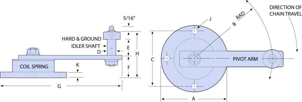
The Murray Series 50 Adjusto-Matic is a screw-adjustable tensioner with a spring-loaded pivot arm. The arm maintains tension on the chain or belt and automatically takes up slack due to cyclic loading or wear. The Series 50 Adjusto-Matic offers the user all the advantages of the Adjusto-Screw plus the automatic take-up feature which substantially reduces maintenance.
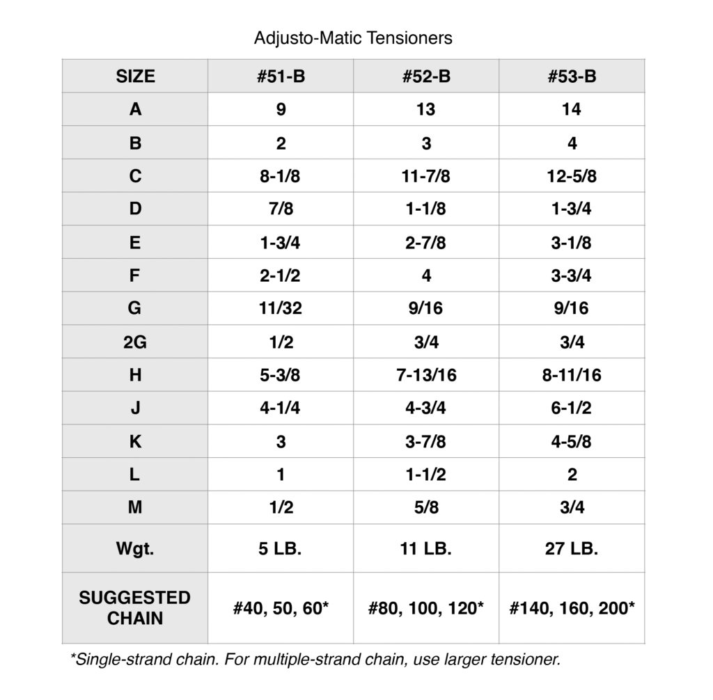
Constructed of structural steel, the Series 50 Adjusto-Matic is a heavy-duty tensioner available in a wide range of sizes capable of handling RC 40 to RC 200 chain. Its double-coil spring is loaded by turning the adjustment screw in the base of the unit, forcing the idler arm against the slack side of the chain.
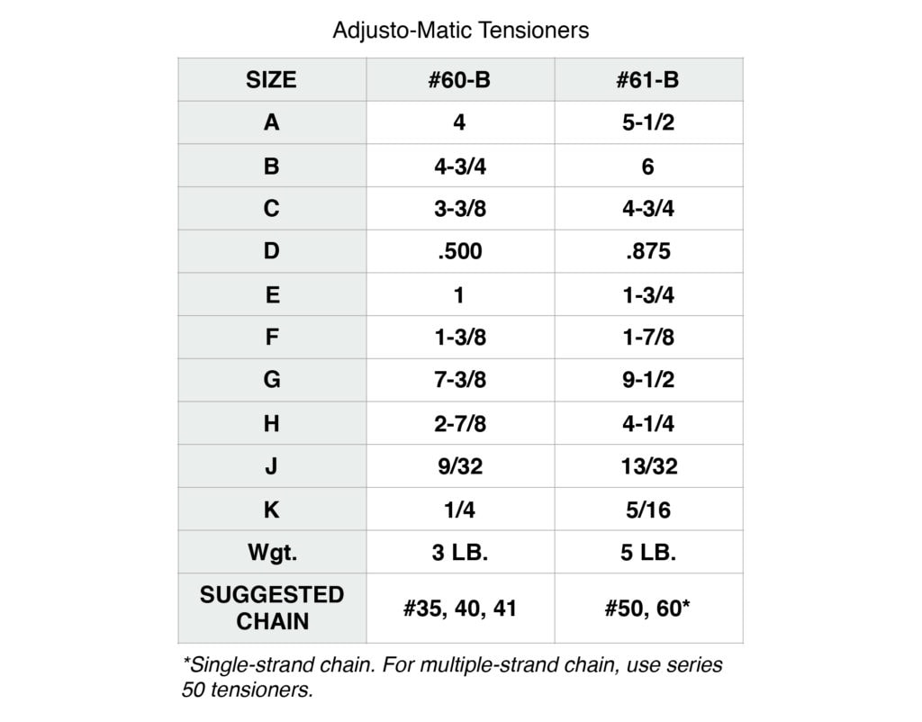
The Series 60 Adjusto-Matic has a spring-loaded pivot arm but does not have the screw-type adjustment. It is used in lighter applications (RC 35 to RC 60 chain) where automatic take-up is desired. Since the pivot arm must be adjusted by hand, the mounting location of the tensioner is important.
On both the Series 50 and 60 tensioners, the pivot arm swings 90°from center line in either direction, however, it must be positioned to swing in the direction of the chain (or belt) travel. For reversing drives, the tensioners are used in pairs; one on slack side and one on the tight side.
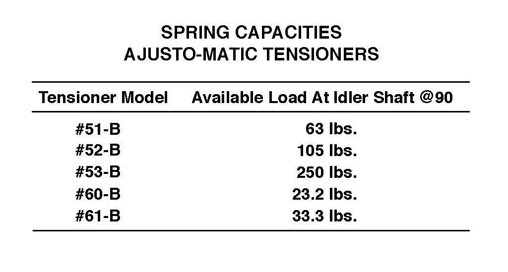
Available load at idler shaft is the maximum amount of force on the chain developed by the spring loaded arm when deflected 90° to either side of the neutral position.
The basic spring preload is 20% of the total capability. The load curve is a straight line proportion of load to angle of deflection.
Depending on application, please allow a service factor for spring capacity. Springs are shot-peened for longer life.
INSTALLATION SUGGESTIONS
- Tensioning that is too tight causes excessive wear on chain, belt and bearings.
- Tensioning that is too loose allows belt slippage or chain vibration, causing loss of horsepower or wear.
- Idlers should be located on the slack side of the drive chain or belt.
- The use of idlers on the back of V-belts causes reverse bend, and can reduce belt life. However, when inside idlers are used, the arc of contact is reduced and allowance must be made for horsepower loss.
- Chain idlers should be run on the outside of the chain.
- Idler sprockets should have at least three teeth engaged with the chain.
- Idlers, when used on the outside of the drive, should be located approximately 1/3 of the center distance from the small pulley or sprocket.
- Idlers, when used on the inside of the drive, should be located approximately 1/3 of the center distance from the large pulley or sprocket.
